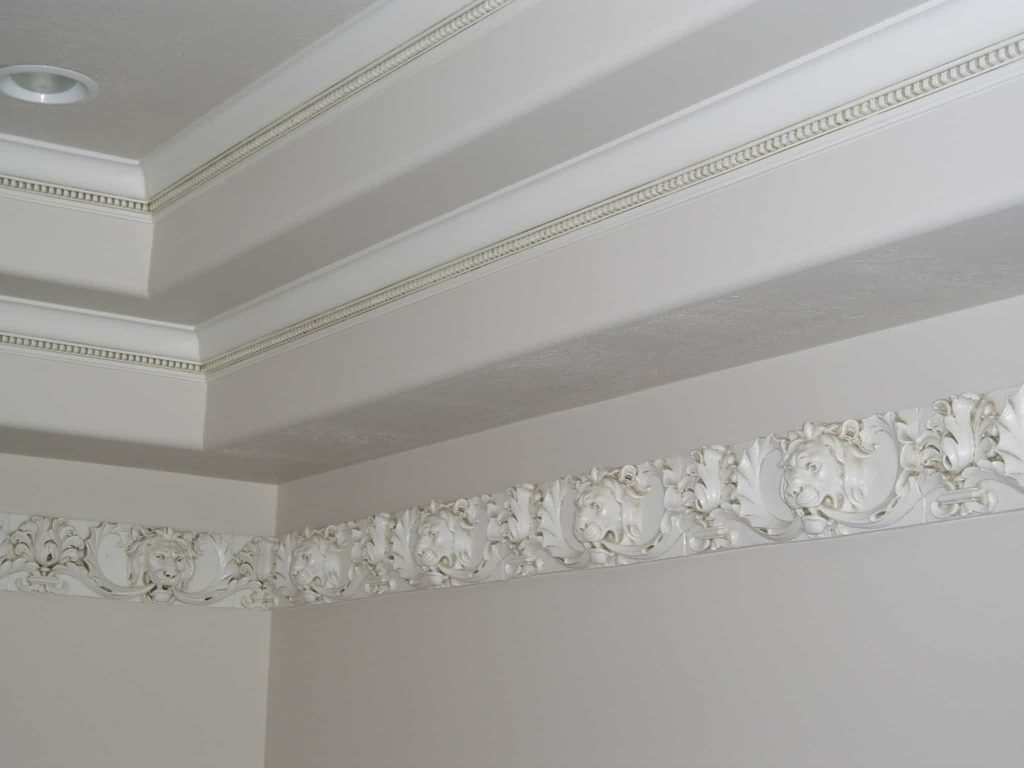
GLASS FIBER REINFORCED GYPSUM (GFRG)
Download PDFs
Product Data
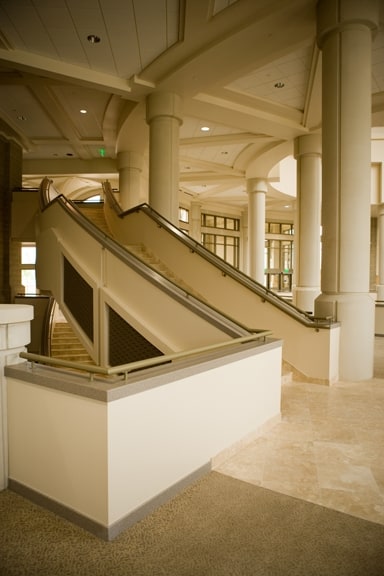
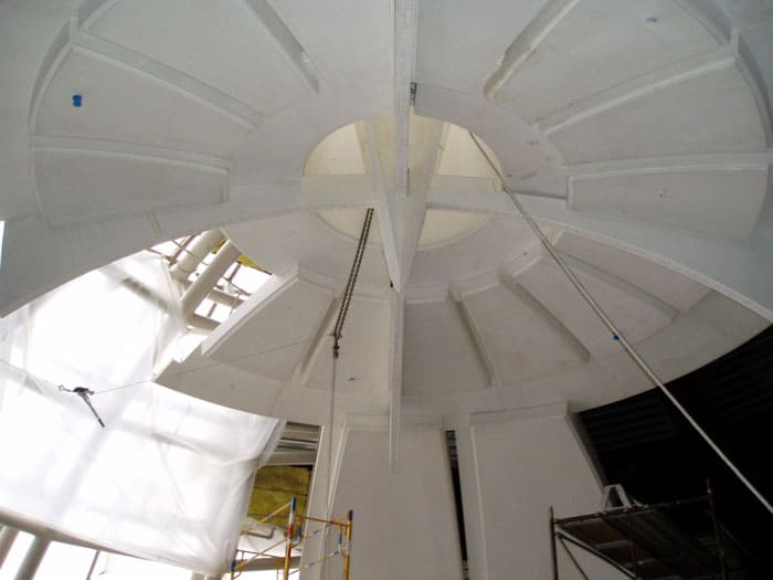
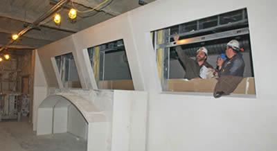
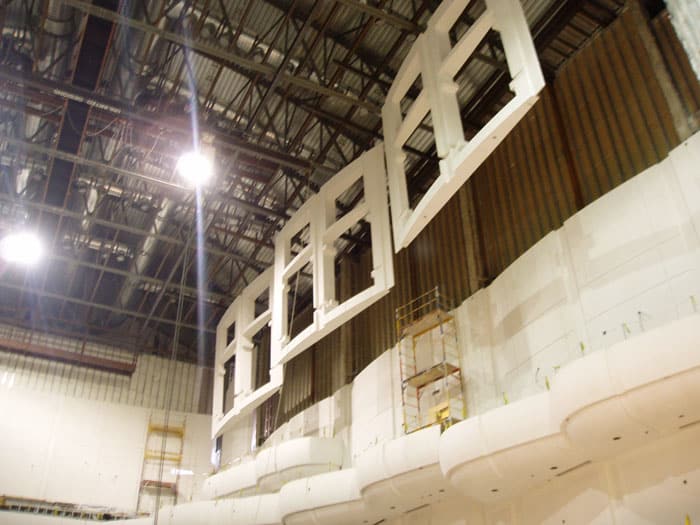
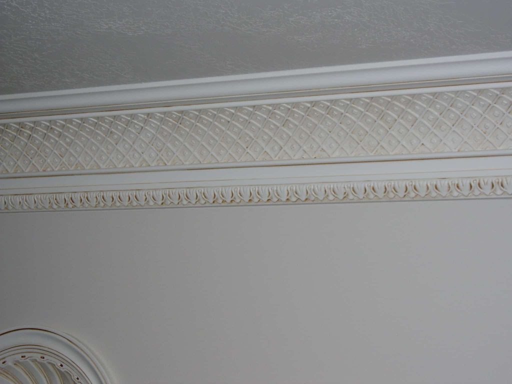
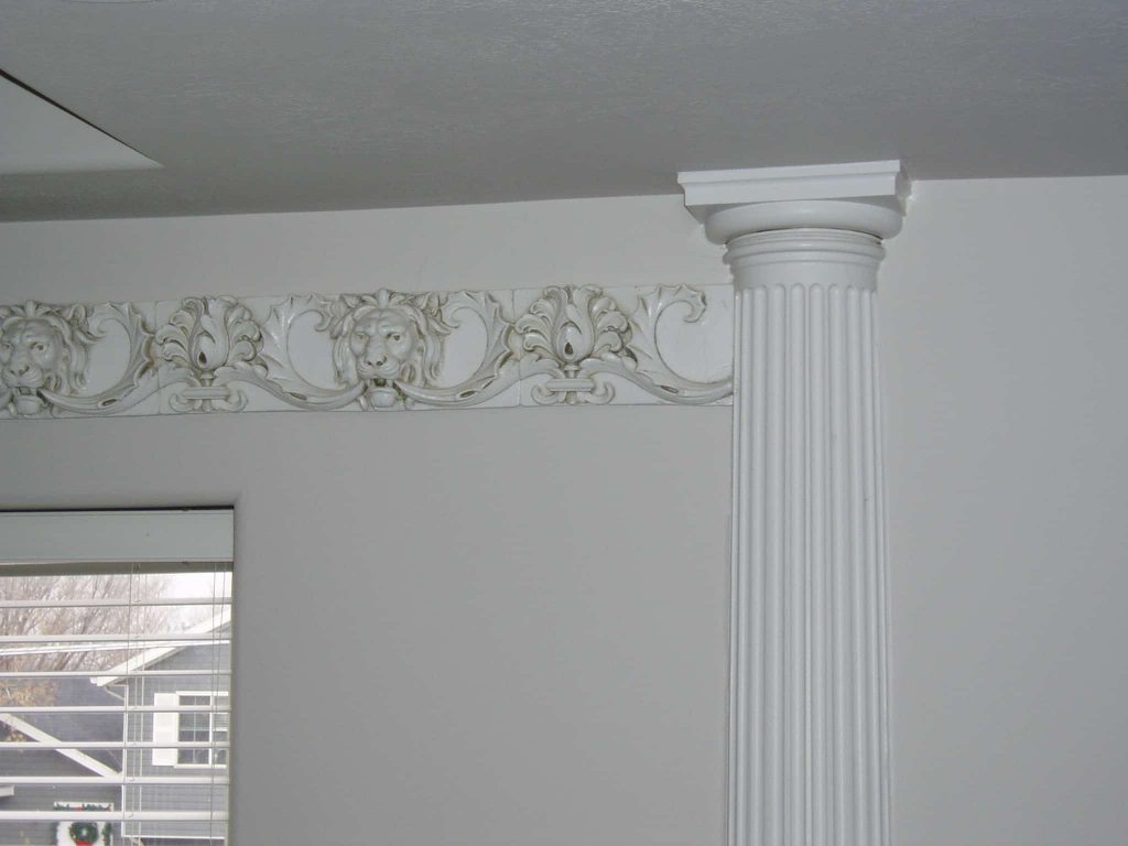
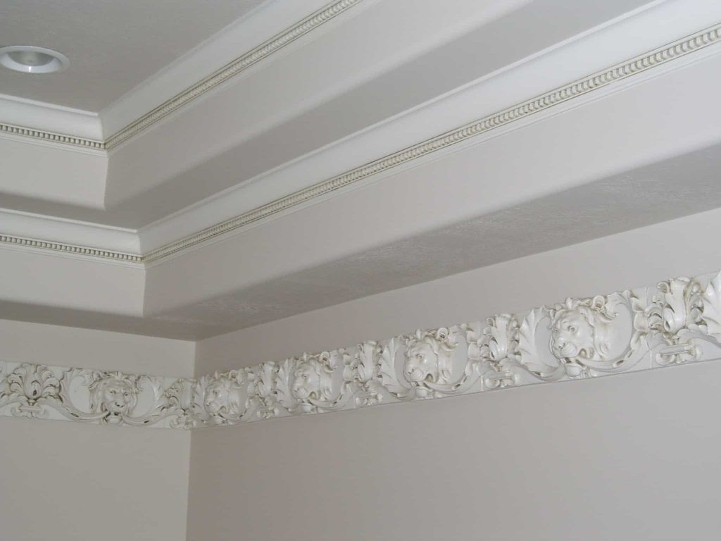
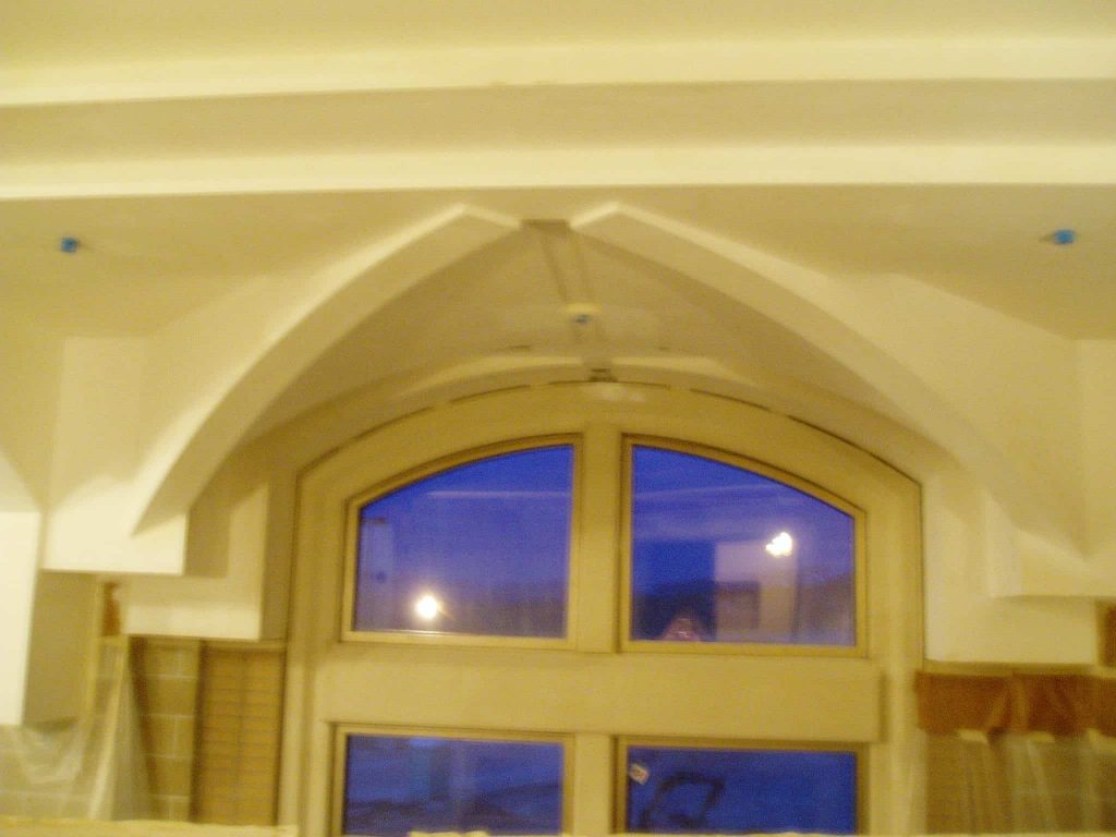
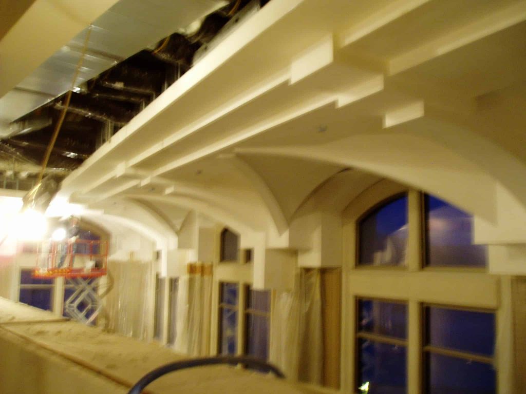
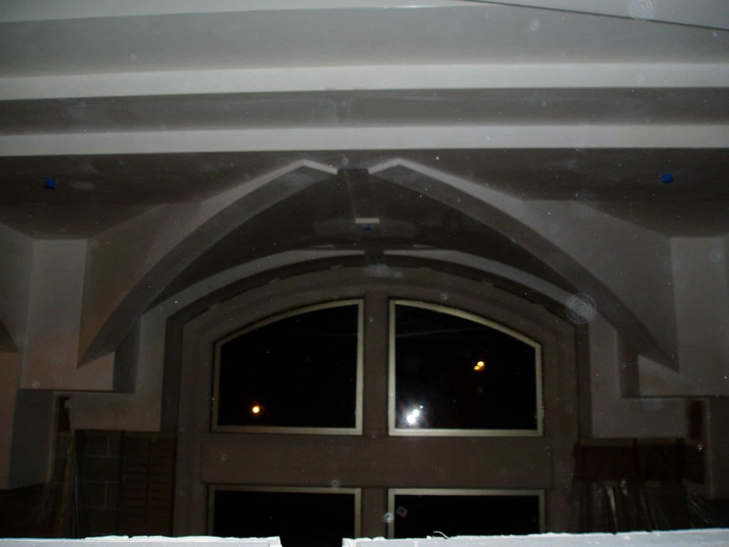
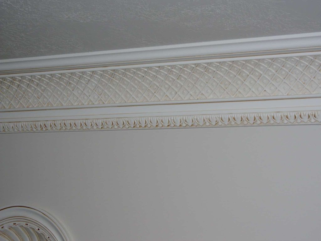
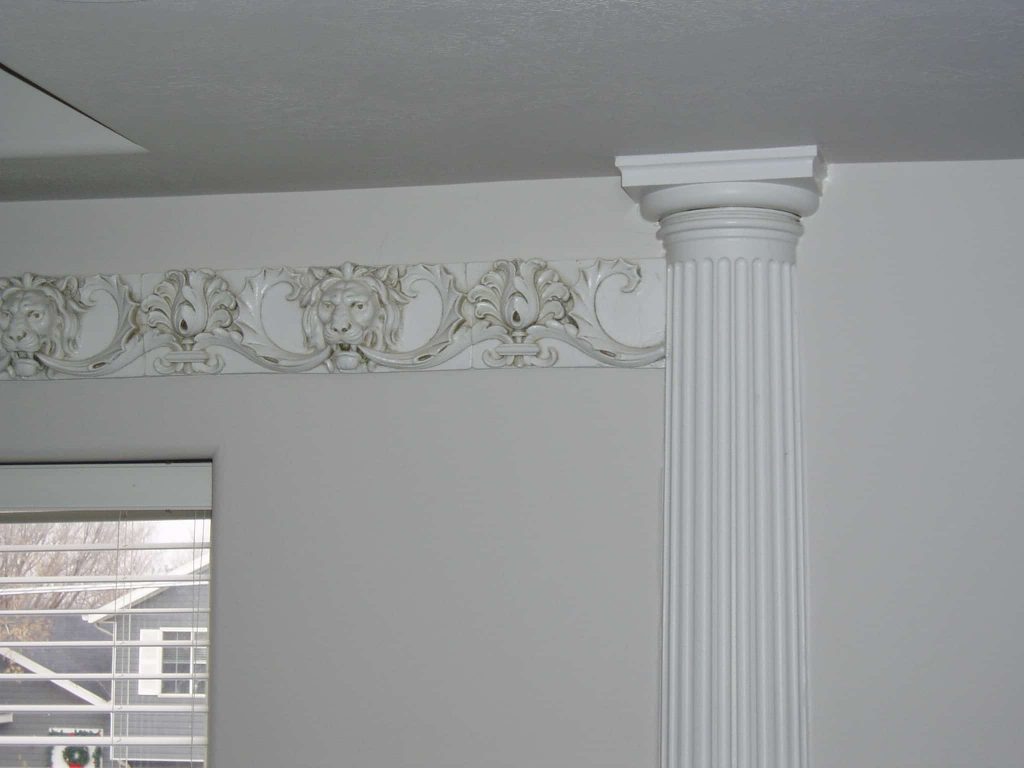
Interior Columns, Domes, Light Coves & Ceiling or Wall Panels
Design
Shop drawings are submitted for verification of profiles, dimensions, and surrounding construction of GFRG units. Recommended attachment details are indicated on the shop drawings. Attachment methods shown on shop drawings are suggestions only. It is the responsibility of the installer to meet all local building codes, verify job conditions and adjust installation procedures accordingly. Some site cutting and/or grinding of parts may be required to suit job conditions. Field shimming may be required.
Testing
| Matrix | Gypsum Cement |
| Glass Fiber | 5-6% weight, Type E 38% by volume |
| Thickness | 3/16” Nominal |
| Flexural Strength | 10, 660 PSI |
| Modulus of Elasticity | 1.43 X 10^6 PSI |
| Ultimate Tensile Strength | 2, 250 PSI (ASTM D638) |
| Modulus of Elasticity | 3.87 X 10^6 PSI |
| Flammability (ASTM E84-81A): | Flame Spread Index -0 Smoke Developed Value -0 Fuel Contributed -0 |
| Impact Strength (ASTM D256) | 12.9 ft. lb/in |
| Thermal Conductivity (ASTM C518) | “C” of 1.56 BTU/hr. ft^2 0F |
| Barcol Hardness (ASTM D2583) | 64 |
| Rockwell Hardness (ASTM D785) | 98.8 ‘M’ Scale |
| Density | 106.4 lbs/ft. ^3 |
| Thermal Coefficient of Expansion (ASTM D696) | 5.4X10^6 in. /in/ /0f |
| Compressive Strength (ASTM C39/C109) | 7, 080 PSI |
| Water Resistance (ASTM C473) | 12.5% Weight Gain |
| Humidified Deflection (ASTM C473) | 1/8” |
| Toxicity NBS/U.S. Testing | Non-Toxic |
Fabrications
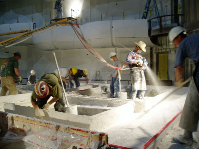
Mix – GFRG is batched and blended in accordance with industry standards using the specified mix design. Prefabricated glass-fiber reinforced gypsum units using multidirectional spray lay-up procedures and combined with gypsum plaster formulated for combination with glass fiber.
Application – GFRG mixture is sprayed and/or hand laid into molds designed to match the shape and dimensions shown on the approved shop drawings. The nominal shell thickness is 3/16”.
Finish – GFRG surface is smooth, ready to receive primer and paint, which is suitable for interior finish.
Delivery
GFRG units are crated or palletized at the plant. Crated units are delivered to the jobsite via truck.
Unloading of crates on site is the responsibility of the installer.
Storage
Store crated GFRG products on a level surface protected from weathering and damage. Do not unpack crates until immediately prior to installation.
Handling
Use special care to prevent damage to material surface; do not allow acidic materials to come in contact with surface, as degradation and discoloration can occur.
Glass Fiber Reinforced Gypsum (GFRG)
Section 09 2700
PART 1 GENERAL
1.1 SECTION INCLUDES
A. Glass fiber reinforced gypsum fabrications of the following types:
1. Access panels.
2. Columns.
3. Moldings and trim.
4. Custom fabrications.
1.2 RELATED SECTIONS
A. Section 05 50 00 – Metal Fabrications.
B. Section 06 10 00 – Rough Carpentry.
C. Section 09 21 16.23 – Gypsum Board Shaft Wall Assemblies.
D. Section 09 90 00 – Painting and Coating.
1.3 REFERENCES
A. ASTM C 840 – Standard Specification for Application and Finishing of Gypsum Board.
B. ASTM E 84 – Standard Test method for Surface Burning Characteristics.
1.4 SUBMITTALS
A. Submit under provisions of Section 01 30 00 – Administrative Requirements.
B. Product Data: Manufacturer’s data sheets on each product to be used, including:
1. Preparation instructions and recommendations
2. Storage and handling requirements and recommendations.
3. Installation methods.
C. Shop Drawings: Indicate overall dimensions, profile and joint treatment.
D. Selection Samples: For each finish product specified, two complete sets of color chips representing manufacturer’s full range of available colors and patterns.
E. Verification Samples: For each finish product specified, two samples, minimum size 6 inches (150 mm) square, representing actual product, color, and patterns.
1.5 QUALITY ASSURANCE
A. Manufacturer Qualifications:
B. Installer Qualifications: Regularly engaged and experienced in the installation of glass fiber reinforced fabrications.
C. Mock-Up: Provide a mock-up for evaluation of surface preparation techniques and application workmanship.
1. Finish areas designated by Architect.
2. Do not proceed with remaining work until workmanship, color, and sheen are approved by Architect.
3. Refinish mock-up area as required to produce acceptable work.
1.6 DELIVERY, STORAGE, AND HANDLING
A. Delivery: GFRG units shall be crated, palletized or loaded onto the delivery truck at the plant. Product is delivered to the jobsite per project requirements.
B. Storage: Store GFRG on a level surface protected from weather, moisture and damage.Product shall be appropriately stored until installation.
C. Handling: GFRG shall be handled to prevent damage to finished surfaces.
1.7 PROJECT CONDITIONS
A. Maintain environmental conditions (temperature, humidity, and ventilation) within limits recommended by manufacturer for optimum results. Do not install products under environmental conditions outside manufacturer’s absolute limits.
1.8 COORDINATION
A. Installation and joint treatment of GFRG shall be as specified under Section 09 21 16.23 – Gypsum Board Shaft Wall Assemblies.
PART 2 PRODUCTS
2.1 MANUFACTURERS
A. Unlimited Designs Inc. 780 North Warm Springs Rd, Salt Lake City, Utah 84116
B. Requests for substitutions will be considered in accordance with provisions of Section 01 60 00 – Product Requirements.
2.2 GLASS FIBER REINFORCED GYPSUM FABRICATI0NS
A. Material: Continuous random filament glass fiber reinforcing of high density gypsum fabrications. Cast or molded as determined by manufacturer. Glass mat and structural reinforcing as determined by manufacturer.
B. Finish: Unfinished to receive field joint treatment and finish. Refer to Section 09 21 16.23 – Gypsum Board Shaft Wall Assemblies and 09900.
C. Physical Characteristics:
1. Glass Content: 5 to 6 percent by weight.
2. Density: 103 to 112 pcf. (1648 kgcm to 1792 kgcm).
3. Flexural Strength: 3000 to 4000 psi (2,068 kPa to 27,579 kPa).
4. Weight: 2.5 to 6 psf (12 kgf/m2 to 30 kgf/m2).
5. Compressive Strength: > 7600 psi (52,400 kPa).
6. Hardness (Barcol): 50.
7. Impact resistance: 8.0 ft lb/sq. inch (0.01 kgf/sq. mm).
8. Surface Burning Characteristics: Flame spread – 0. Smoke developed – 0.
9. Shell Thickness: 1/8 inch to 3/16 inch (3 to 5 mm) nominal.
10. Tolerances:
a. Draft Angle: 3 degrees minimum on returns, setbacks, reveals and grooves.
b. Shell Thickness: +1/16, -0 inches (+1.5 mm, -0 mm).
c. Overall Thickness Dimension: +1/8, -1/8 inches (+3 mm, -3 mm).
d. Variation from Dimensions: +1/8, -1/8 inches (+3 mm, -3 mm).
e. Warpage or Bowing: +1/16, -1/16 (+1.5 mm, -1.5 mm).
D. Fabrication:
1. Mix: GFRG shall be batched and blended in accordance with ASTM 1355 using the specified mix design.
2. Application: GFRG mixture shall be hand applied into approved molds that correspond with the approved shop drawings. GFRG shall be then removed from the molds and placed into jigs until cured. Product shall be labeled corresponding to the approved shop drawings.
3. Finish: GFRG surface is a level four equivalent finish ready to receive primer and paint.
2.3 ACCESS PANELS
A. Standard Access Panel: Glass fiber reinforced gypsum surround frame and drop-in rectangular door.
1. Product: Stealth Access Panels as manufactured by GC Products Inc.
2. Panel consists of a surround frame with wood embedment and pre-spotted drill holes for installation. The residential panels include an energy saving gasket to keep air from infiltrating the living space.
3. Residential Access Panel Opening Size (With Gasket):
a. Model TR-APGR2230: 22 inches by 30 inches (559 mm by 762 mm).
b. Model TR-APGR3030: 30 inches by 30 inches (762 mm by 762 mm).
4. Commercial Access Panel Opening Size:
a. Model TR-AP009: 9 inches by 9 inches (229 mm by 229 mm).
b. Model TR-AP012: 12 inches by 12 inches (305 mm by 305 mm).
c. c.Model TR-AP016: 16 inches by 16 inches (406 mm by 406 mm).
d. Model TR-AP018: 18 inches by 18 inches (457 mm by 457 mm).
e. Model TR-AP024: 24 inches by 24 inches (610 mm by 610 mm).
B. Round Access Panel: Glass fiber reinforced gypsum surround frame and drop-in round door.
1. Product: Stealth Access Panels as manufactured by GC Products Inc.
2. Access Panel Opening Size (Rough opening):
a. Model TR-RAP0 12: 12 inches (305 mm) diameter (18 inches by 18 inches (457 mm by 457 mm) rough opening).
b. Model TR-RAP016: 16 inches (406 mm) diameter (22 inches by 22 inches (559 mm by 559 mm) rough opening).
c. Model TR-RAP018: 18 inches (457 mm) diameter (24 inches by 24 inches (610 mm by 610 mm) rough opening).
d. Model TR-RAP024: 24 inches (610 mm) diameter (30 inches by 30 inches (762 mm by 762 mm) rough opening).
C. Hinged Access Panel: Glass fiber reinforced gypsum surround frame and hinged door with lock.
1. Product: Stealth Access Panels as manufactured by GC Products Inc.
2. Access Panel Opening Size:
a. TR-HAP009: 9 inches by 9 inches (229 mm by 229 mm).
b. TR-HAP012: 12 inches by 12 inches (305 mm by 305 mm).
c. TR-HAP016: 16 inches by 16 inches (406 mm by 406 mm).
d. TR-HAP018: 18 inches by 18 inches (457 mm by 457 mm).
e. TR-HAP024: 24 inches by 24 inches (610 mm by 610 mm).
D. Fabrication:
1. Physical Characteristics:
a. Shell Thickness: 1/8 inch to 3/16 inch (3 mm to 4.8 mm).
b. Fastener Test Pull Out (wood stud): 525 lb (238 kg) avg.
c. Fastener Test Pull Out (metal stud): 215 lb (98 kg) avg.
d. Fastener Push Through Test: 350 lb (159 kg) avg.
e. Fuel Contribution (ASTM E84): 0.
f. Flame Spread (ASTM E84): 0.
g. Smoke Index (ASTM E84): 0.
h. Combustion (ASTM E84): Non-combustible.
i. Class A Non-Rated.
2. Material: Units shall be prefabricated with high-density gypsum, reinforced with continuous random filament glass fiber mat and structural reinforcing as specified.
2.4 COLUMNS
A. Product: GFRG Columns as manufactured by GC Products Inc.
B. Columns with Base and Capital:
1. Shaft Type: Straight.
2. Shaft Type: Tapered.
3. Shaft Type: Closed fluted.
4. Shaft Type: Open fluted.
5. Shaft Style: Standard Straight.
6. Shaft Style: Offset Segmented.
7. Shaft Style: Segmented.
8. Shaft Size: As indicated or required by the drawings.
9. Shaft Size: 12 inch (305 mm) shaft diameter.
10. Shaft Size: 16 inch (406 mm) shaft diameter.
11. Shaft Size: 18 inch (457 mm) shaft diameter.
12. Shaft Size: 24 inch (610 mm) shaft diameter.
13. Base and capital style as indicated on the drawings.
14. Provide either tape or caulk joint as indicated or required by the drawings.
C. Columns Covers:
1. Shaft Type: Straight round.
2. Shaft Type: Tapered round.
3. Shaft Type: Square.
4. Shaft Type: Elliptical.
5. Shaft Style: Standard Straight.
6. Shaft Style: Offset Segmented.
7. Shaft Style: Segmented.
8. Shaft Size: As indicated or required by the drawings.
9. Provide either tape or caulk joint as indicated or required by the drawings.
2.5 MOULDINGS AND TRIM
A. Product: GFRG Columns as manufactured by GC Products Inc.
B. Types and Profiles: Provide the following moulding and trim as indicated on the drawings:
1. Moulding profiles and sizes as indicated.
2. Cornice profiles and sizes as indicated.
3. Light cove profiles and sizes as indicated.
4. Light cove and reflector profiles and sizes as indicated.
5. Base board profiles and sizes as indicated.
6. Ceiling dome profiles and sizes as indicated.
7. GFRC veneer wall panels and wall trim profiles and sizes as indicated.
2.6 CUSTOM FABRICATI0NS
A. Themed Environments:
B. Historical Restoration:
PART 3 EXECUTION
3.1 EXAMINATION
A. Do not begin installation until substrates have been properly prepared.
B. If substrate preparation is the responsibility of another installer, notify Architect of unsatisfactory preparation before proceeding.
C. Verify field dimensions before beginning installation.
3.2 PREPARATION
A. Clean surfaces thoroughly prior to installation.
B. Prepare surfaces using the methods recommended by the manufacturer for achieving the best result for the substrate under the project conditions.
C. Install temporary and permanent supplementary supports as required for proper installation.
3.3 INSTALLATION
A. Install in accordance with applicable code and manufacturer’s instructions, plumb and true to line, shims were necessary.
B. Provide expansion joints where moving joints occur in the supporting substrate.
C. Install Stealth Frame with #6 buglehead screws in countersunk holes in frame.
D. Coordinate work with Section 09 21 16.23 – Gypsum Board Shaft Wall Assemblies. Join pieces with cemented butt joints and finish joints. Joint treatment shall comply with ASTM C 840 – Level 5 finish treatment.
3.4 PROTECTION
A. Protect installed products until completion of project.
B. Touch-up, repair or replace damaged products before Substantial Completion.
Glass Fiber Reinforced Gypsum (GFRG)
Section 09 2700
PART 1 GENERAL
1.1 SECTION INCLUDES
A. Glass fiber reinforced gypsum fabrications of the following types:
1. Access panels.
2. Columns.
3. Moldings and trim.
4. Custom fabrications.
1.2 RELATED SECTIONS
A. Section 05 50 00 – Metal Fabrications.
B. Section 06 10 00 – Rough Carpentry.
C. Section 09 21 16.23 – Gypsum Board Shaft Wall Assemblies.
D. Section 09 90 00 – Painting and Coating.
1.3 REFERENCES
A. ASTM C 840 – Standard Specification for Application and Finishing of Gypsum Board.
B. ASTM E 84 – Standard Test method for Surface Burning Characteristics.
1.4 SUBMITTALS
A. Submit under provisions of Section 01 30 00 – Administrative Requirements.
B. Product Data: Manufacturer’s data sheets on each product to be used, including:
1. Preparation instructions and recommendations
2. Storage and handling requirements and recommendations.
3. Installation methods.
C. Shop Drawings: Indicate overall dimensions, profile and joint treatment.
D. Selection Samples: For each finish product specified, two complete sets of color chips representing manufacturer’s full range of available colors and patterns.
E. Verification Samples: For each finish product specified, two samples, minimum size 6 inches (150 mm) square, representing actual product, color, and patterns.
1.5 QUALITY ASSURANCE
A. Manufacturer Qualifications:
B. Installer Qualifications: Regularly engaged and experienced in the installation of glass fiber reinforced fabrications.
C. Mock-Up: Provide a mock-up for evaluation of surface preparation techniques and application workmanship.
1. Finish areas designated by Architect.
2. Do not proceed with remaining work until workmanship, color, and sheen are approved by Architect.
3. Refinish mock-up area as required to produce acceptable work.
1.6 DELIVERY, STORAGE, AND HANDLING
A. Delivery: GFRG units shall be crated, palletized or loaded onto the delivery truck at the plant. Product is delivered to the jobsite per project requirements.
B. Storage: Store GFRG on a level surface protected from weather, moisture and damage.Product shall be appropriately stored until installation.
C. Handling: GFRG shall be handled to prevent damage to finished surfaces.
1.7 PROJECT CONDITIONS
A. Maintain environmental conditions (temperature, humidity, and ventilation) within limits recommended by manufacturer for optimum results. Do not install products under environmental conditions outside manufacturer’s absolute limits.
1.8 COORDINATION
A. Installation and joint treatment of GFRG shall be as specified under Section 09 21 16.23 – Gypsum Board Shaft Wall Assemblies.
PART 2 PRODUCTS
2.1 MANUFACTURERS
A. Unlimited Designs Inc. 780 North Warm Springs Rd, Salt Lake City, Utah 84116
B. Requests for substitutions will be considered in accordance with provisions of Section 01 60 00 – Product Requirements.
2.2 GLASS FIBER REINFORCED GYPSUM FABRICATI0NS
A. Material: Continuous random filament glass fiber reinforcing of high density gypsum fabrications. Cast or molded as determined by manufacturer. Glass mat and structural reinforcing as determined by manufacturer.
B. Finish: Unfinished to receive field joint treatment and finish. Refer to Section 09 21 16.23 – Gypsum Board Shaft Wall Assemblies and 09900.
C. Physical Characteristics:
1. Glass Content: 5 to 6 percent by weight.
2. Density: 103 to 112 pcf. (1648 kgcm to 1792 kgcm).
3. Flexural Strength: 3000 to 4000 psi (2,068 kPa to 27,579 kPa).
4. Weight: 2.5 to 6 psf (12 kgf/m2 to 30 kgf/m2).
5. Compressive Strength: > 7600 psi (52,400 kPa).
6. Hardness (Barcol): 50.
7. Impact resistance: 8.0 ft lb/sq. inch (0.01 kgf/sq. mm).
8. Surface Burning Characteristics: Flame spread – 0. Smoke developed – 0.
9. Shell Thickness: 1/8 inch to 3/16 inch (3 to 5 mm) nominal.
10. Tolerances:
a. Draft Angle: 3 degrees minimum on returns, setbacks, reveals and grooves.
b. Shell Thickness: +1/16, -0 inches (+1.5 mm, -0 mm).
c. Overall Thickness Dimension: +1/8, -1/8 inches (+3 mm, -3 mm).
d. Variation from Dimensions: +1/8, -1/8 inches (+3 mm, -3 mm).
e. Warpage or Bowing: +1/16, -1/16 (+1.5 mm, -1.5 mm).
D. Fabrication:
1. Mix: GFRG shall be batched and blended in accordance with ASTM 1355 using the specified mix design.
2. Application: GFRG mixture shall be hand applied into approved molds that correspond with the approved shop drawings. GFRG shall be then removed from the molds and placed into jigs until cured. Product shall be labeled corresponding to the approved shop drawings.
3. Finish: GFRG surface is a level four equivalent finish ready to receive primer and paint.
2.3 ACCESS PANELS
A. Standard Access Panel: Glass fiber reinforced gypsum surround frame and drop-in rectangular door.
1. Product: Stealth Access Panels as manufactured by GC Products Inc.
2. Panel consists of a surround frame with wood embedment and pre-spotted drill holes for installation. The residential panels include an energy saving gasket to keep air from infiltrating the living space.
3. Residential Access Panel Opening Size (With Gasket):
a. Model TR-APGR2230: 22 inches by 30 inches (559 mm by 762 mm).
b. Model TR-APGR3030: 30 inches by 30 inches (762 mm by 762 mm).
4. Commercial Access Panel Opening Size:
a. Model TR-AP009: 9 inches by 9 inches (229 mm by 229 mm).
b. Model TR-AP012: 12 inches by 12 inches (305 mm by 305 mm).
c. c.Model TR-AP016: 16 inches by 16 inches (406 mm by 406 mm).
d. Model TR-AP018: 18 inches by 18 inches (457 mm by 457 mm).
e. Model TR-AP024: 24 inches by 24 inches (610 mm by 610 mm).
B. Round Access Panel: Glass fiber reinforced gypsum surround frame and drop-in round door.
1. Product: Stealth Access Panels as manufactured by GC Products Inc.
2. Access Panel Opening Size (Rough opening):
a. Model TR-RAP0 12: 12 inches (305 mm) diameter (18 inches by 18 inches (457 mm by 457 mm) rough opening).
b. Model TR-RAP016: 16 inches (406 mm) diameter (22 inches by 22 inches (559 mm by 559 mm) rough opening).
c. Model TR-RAP018: 18 inches (457 mm) diameter (24 inches by 24 inches (610 mm by 610 mm) rough opening).
d. Model TR-RAP024: 24 inches (610 mm) diameter (30 inches by 30 inches (762 mm by 762 mm) rough opening).
C. Hinged Access Panel: Glass fiber reinforced gypsum surround frame and hinged door with lock.
1. Product: Stealth Access Panels as manufactured by GC Products Inc.
2. Access Panel Opening Size:
a. TR-HAP009: 9 inches by 9 inches (229 mm by 229 mm).
b. TR-HAP012: 12 inches by 12 inches (305 mm by 305 mm).
c. TR-HAP016: 16 inches by 16 inches (406 mm by 406 mm).
d. TR-HAP018: 18 inches by 18 inches (457 mm by 457 mm).
e. TR-HAP024: 24 inches by 24 inches (610 mm by 610 mm).
D. Fabrication:
1. Physical Characteristics:
a. Shell Thickness: 1/8 inch to 3/16 inch (3 mm to 4.8 mm).
b. Fastener Test Pull Out (wood stud): 525 lb (238 kg) avg.
c. Fastener Test Pull Out (metal stud): 215 lb (98 kg) avg.
d. Fastener Push Through Test: 350 lb (159 kg) avg.
e. Fuel Contribution (ASTM E84): 0.
f. Flame Spread (ASTM E84): 0.
g. Smoke Index (ASTM E84): 0.
h. Combustion (ASTM E84): Non-combustible.
i. Class A Non-Rated.
2. Material: Units shall be prefabricated with high-density gypsum, reinforced with continuous random filament glass fiber mat and structural reinforcing as specified.
2.4 COLUMNS
A. Product: GFRG Columns as manufactured by GC Products Inc.
B. Columns with Base and Capital:
1. Shaft Type: Straight.
2. Shaft Type: Tapered.
3. Shaft Type: Closed fluted.
4. Shaft Type: Open fluted.
5. Shaft Style: Standard Straight.
6. Shaft Style: Offset Segmented.
7. Shaft Style: Segmented.
8. Shaft Size: As indicated or required by the drawings.
9. Shaft Size: 12 inch (305 mm) shaft diameter.
10. Shaft Size: 16 inch (406 mm) shaft diameter.
11. Shaft Size: 18 inch (457 mm) shaft diameter.
12. Shaft Size: 24 inch (610 mm) shaft diameter.
13. Base and capital style as indicated on the drawings.
14. Provide either tape or caulk joint as indicated or required by the drawings.
C. Columns Covers:
1. Shaft Type: Straight round.
2. Shaft Type: Tapered round.
3. Shaft Type: Square.
4. Shaft Type: Elliptical.
5. Shaft Style: Standard Straight.
6. Shaft Style: Offset Segmented.
7. Shaft Style: Segmented.
8. Shaft Size: As indicated or required by the drawings.
9. Provide either tape or caulk joint as indicated or required by the drawings.
2.5 MOULDINGS AND TRIM
A. Product: GFRG Columns as manufactured by GC Products Inc.
B. Types and Profiles: Provide the following moulding and trim as indicated on the drawings:
1. Moulding profiles and sizes as indicated.
2. Cornice profiles and sizes as indicated.
3. Light cove profiles and sizes as indicated.
4. Light cove and reflector profiles and sizes as indicated.
5. Base board profiles and sizes as indicated.
6. Ceiling dome profiles and sizes as indicated.
7. GFRC veneer wall panels and wall trim profiles and sizes as indicated.
2.6 CUSTOM FABRICATI0NS
A. Themed Environments:
B. Historical Restoration:
PART 3 EXECUTION
3.1 EXAMINATION
A. Do not begin installation until substrates have been properly prepared.
B. If substrate preparation is the responsibility of another installer, notify Architect of unsatisfactory preparation before proceeding.
C. Verify field dimensions before beginning installation.
3.2 PREPARATION
A. Clean surfaces thoroughly prior to installation.
B. Prepare surfaces using the methods recommended by the manufacturer for achieving the best result for the substrate under the project conditions.
C. Install temporary and permanent supplementary supports as required for proper installation.
3.3 INSTALLATION
A. Install in accordance with applicable code and manufacturer’s instructions, plumb and true to line, shims were necessary.
B. Provide expansion joints where moving joints occur in the supporting substrate.
C. Install Stealth Frame with #6 buglehead screws in countersunk holes in frame.
D. Coordinate work with Section 09 21 16.23 – Gypsum Board Shaft Wall Assemblies. Join pieces with cemented butt joints and finish joints. Joint treatment shall comply with ASTM C 840 – Level 5 finish treatment.
3.4 PROTECTION
A. Protect installed products until completion of project.
B. Touch-up, repair or replace damaged products before Substantial Completion


